This story starts with a trip to my corner hardware store to replace a toilet that
was not repairable. They had just two models for sale, both made by American Standard.
The first was a basic model called the Cadet Pro and the second was a somewhat more
expensive model called the Champion that was billed as having a more powerful flush
due to its 4 inch flush vale. (The Cadet like most modern toilets has a 3 inch flush
valve). My usual instinct would have led me to the basic model which would have been the
wiser choice in this case. However the Champion was on sale and because of that it was
only $15 more expensive than the Cadet. A bigger flush valve is got to be a good idea,
right? So I brought home the American Standard Champion toilet.
With all toilets I have used, pushing the lever lifts the flapper valve which
sends the water in the tank to the bowl. When you release the lever, the flapper
takes a few seconds to descend giving time for most of the water in the tank to flush
the bowl. My first flush after the installation was with the lid off and I could see
something different right away. As soon as I released the lever, the flapper immediately
fell onto the flush valve seat shutting off the water entering the bowl. To get a complete
flush I would have to hold down the lever until all the water in the tank was used.
With other toilets the lever would have to be held down like that only when something in
the toilet was broken or misadjusted, or perhaps all the time with some very old toilets.
So I went online to see how to fix the problem. That's when I saw the reviews. Some
customers didn't realize you had to hold down the lever and just complained that the toilet
had a very weak flush. Most customers figured out you need to hold the handle down for a
couple of seconds but didn't like that at all and were frustrated that there was no way to
fix it. A contractor had written that once he advised a client about the need to hold the
lever down during the flush the clients always chose some other model. A plumber had written
that the only way he had found to fix the problem was to replace the whole flush valve with
a standard three inch valve. (He didn't say how he accomplished that but I think it would
require replacing the whole tank.) I thought replacing the flush valve was beyond my expertise
so I just used the toilet as is. I did get used to it but after a few weeks I realized it
annoyed me a little more every day. I really didn't want to think about how long I was holding
down the lever ... too long and wasting water and time, or too short and not getting a complete
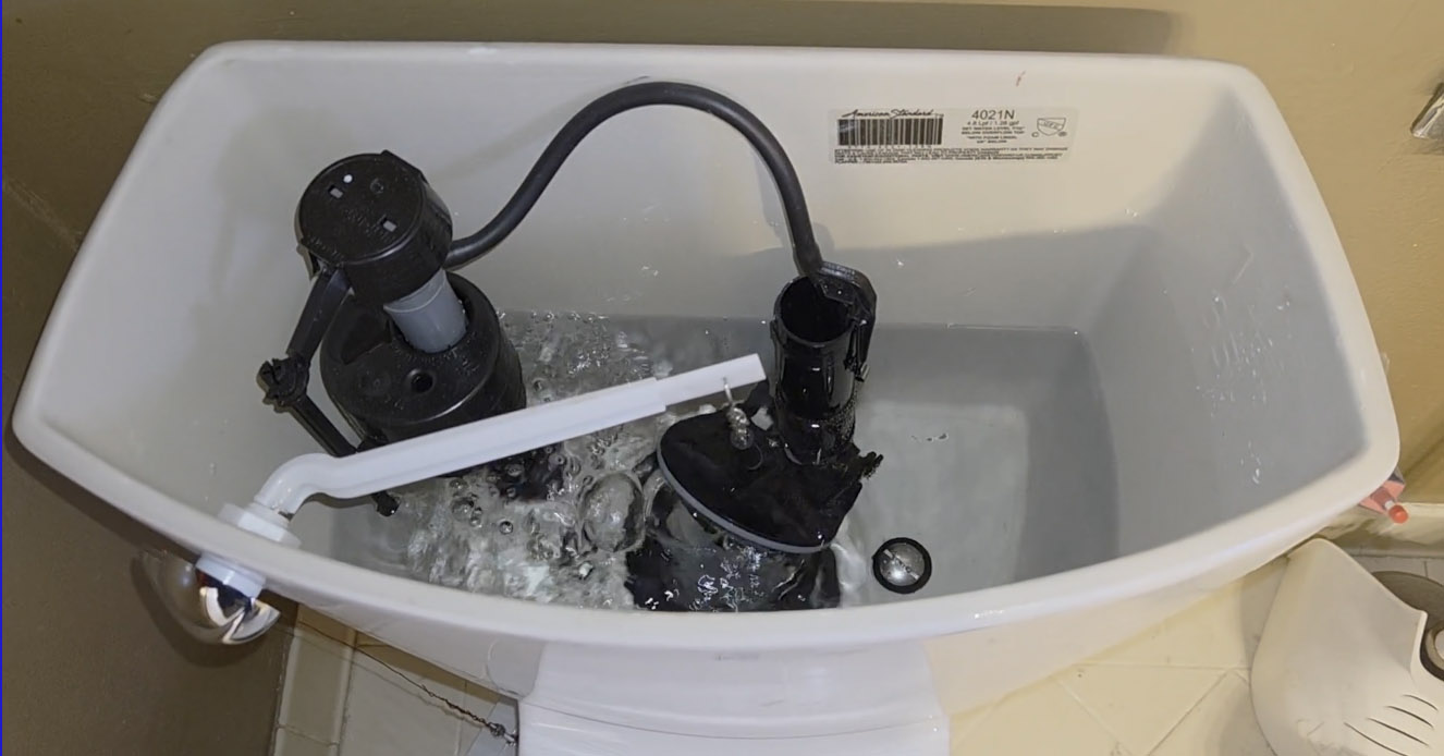
flush. A solution occurred to me that perhaps the plumber who wrote in didn't think of. I tied
a float onto the chain that connects to the flapper thinking the float would slow the flapper
descent giving time for a complete flush. I found that the flapper closes with a fairly high
force requiring a surprisingly large float to make only a marginal improvement.
I thought I could continue to go to larger and larger floats, but no. At a certain
point the float was so strong that when the tank was full it would pull up on the flapper
strongly enough that it wouldn't create a full seal with the value seat and the tank would start
leaking. Once I saw that I realized a float would never work as a solution to this problem.
Perhaps that plumber tried and failed with this approach as well. So I went back
to the hardware store to see if I could return the toilet, but I was one day past their 30 day
return policy.
 It was then my electrical engineering brain kicked in and it occurred to me that a solenoid could
do the flush for me and it could be timed to hold down the lever for the optimal time. It didn't
take me long to come up with this circuit. There is no electrical outlet near my toilet so it would
need to be battery powered. I didn't want to design my own charging circuit, so I decided to use a
standard USB power bank. I estimated that it would take a fairly high powered solenoid to pull the
lever so I chose a 44 watt solenoid from the DigiKey listings. Power banks usually supply about 2 or
3 amps which isn't enough for the nearly 9 amps needed by the solenoid, so I used super-capacitors to
store the energy needed to power the solenoid.
It was then my electrical engineering brain kicked in and it occurred to me that a solenoid could
do the flush for me and it could be timed to hold down the lever for the optimal time. It didn't
take me long to come up with this circuit. There is no electrical outlet near my toilet so it would
need to be battery powered. I didn't want to design my own charging circuit, so I decided to use a
standard USB power bank. I estimated that it would take a fairly high powered solenoid to pull the
lever so I chose a 44 watt solenoid from the DigiKey listings. Power banks usually supply about 2 or
3 amps which isn't enough for the nearly 9 amps needed by the solenoid, so I used super-capacitors to
store the energy needed to power the solenoid.
To see how the circuit works, first imagine the simpler circuit without the relay. The power bank
charges the capacitors thru the resister. After about 20 seconds there would be enough energy
stored in the capacitors to engage the solenoid when the pushbutton was pushed. The solenoid
would disengage as soon as you let go of the pushbutton, and so the circuit would suffer the same
problem of the original lever. This is were the relay comes in. When the pushbutton closes, at the
same time current begins to flow thru the solenoid, current also flows thru the diode to power the relay.
Once the relay closes, the solenoid then gets its current from the capacitors thru the relay and
stays engaged until most of the energy in the capacitors is depleted.
Parts
CAPACITOR: DigiKey #4688-CHP5R0L105R-TW-ND ($2.96) 1F 5V super capacitor, ESR 0.2Ω @1kHz:
spec sheet
CAPACITOR: DigiKey #4688-CHP5R5L405R-TWX-ND ($3.91) 4F 5.5V super capacitor, ESR 0.09Ω @1kHz:
spec sheet
I used 1F capacitors to allow me to adjust the flush time by adding or removing capacitors in parallel.
My first guess was to use 3 capacitors and this produced a flush long enough to empty about 3/4 of the tank.
Unless you are trying to flush most of a roll of toilet paper that should be enough water for any normal flush.
But I chose to add one more capacitor. At 4F the flush was long enough (about 3.6 seconds) to use most of the
water in the tank. I didn't try 5F since I don't think that would have produced a bigger flush. The
capacitance you will need probably would depend on your construction, location of the enclosure, lever
attachment point, and flush preference. If you prefer to use fewer components, the 4F capacitor listed here
would be a good choice and would probably give you a lower leakage current allowing the power bank to last
longer.
SOLENOID: DigiKey #1144-DSOL-1351-05E-ND ($23.49) 44W pull type solenoid with 1 inch stroke:
spec sheet
RELAY: DigiKey #J107F1AS125VDC.36 ($1.09) General Purpose SPST 12A 5V relay:
spec sheet
Alternative relay from Amazon:
spec sheet
RESISTOR: 2.7Ω
I would suggest at least 2 watt resistor, although if you have a small child around you might want to use
a 10 watt resistor instead so it wouldn't burn out even if the button was held down continuously.
I happened to find a 1 watt resister of the right value in my parts box so I used that. I chose a value
low enough to ensure that the capacitors would be recharged by the time the tank refilled which is about
a minute. I found that it would flush again after waiting just 15 seconds or so, but of course that is
a pretty weak flush since there isn't yet enough water in the tank for a strong flush.
PUSH BUTTON:
Any momentary
pushbutton will work and I found one in one of my parts boxes that was just the size I was looking for.
DIODE: 1N5340
The shutoff voltage for the 5V relay is fairly low so I added the diode to make sure the relay would disengage.
This particular diode is a zener diode, but that was unintentional. I had just picked up the first diode I saw
in my junk box which happened to be a zener. A rectifier diode would make more sense, although actually pretty
much any silicon diode would work. Later I tried shorting out the diode with a clip lead to see if it was
really needed, and indeed the relay never disengaged and the resister would have soon burned out if I didn't
quickly remove the clip lead.
POWER BANK: Voltaic Systems V50.
At first I used a power bank I had laying around, but I found that it didn't work. Like most
power banks, it shuts itself off when it doesn't detect a device plugged in that needs to be charged.
The leakage current of the super capacitors is in the micro-amp range which is not high enough
to be recognized by the power bank so soon after the capacitors are charged the powerbank shuts itself off.
At that point the voltage on the super capacitors will start to decay slowly due to the leakage current and
after about 10 hours the voltage would be too low to fire the solenoid. To solve that problem we need a
power bank that is advertised as being "always on" such as this one.
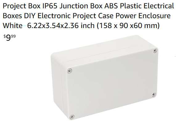
ENCLOSURE: Plastic project box (Amazon).
To test out my circuit I didn't use the enclosure. Instead I just secured it to the side of the toilet using
packing tape. Surprisingly, the circuit worked the first time and I only needed to retape it once to adjust
the timing by adding one more capacitor. There are hundreds of boxes I could have chosen on Amazon.
Construction
 I took the plunger out of the solenoid to attach this braided wire to one end. (There is nothing holding the
plunger into the solenoid.) I also added a thin layer of felt to the pointed end. Without the felt, the solenoid
makes a sharp clacking sound as it engages. You may find the sound satisfying, although with the felt you will
barely hear the solenoid engage. As you will see in the next picture, I attached a screw to the other end of
the braided wire. Then on the other end of the screw I attached a solid copper wire which connects to the toilet
flush level. I used the screw for this purpose because it allowed me to easily adjust the tension on the wire.
I took the plunger out of the solenoid to attach this braided wire to one end. (There is nothing holding the
plunger into the solenoid.) I also added a thin layer of felt to the pointed end. Without the felt, the solenoid
makes a sharp clacking sound as it engages. You may find the sound satisfying, although with the felt you will
barely hear the solenoid engage. As you will see in the next picture, I attached a screw to the other end of
the braided wire. Then on the other end of the screw I attached a solid copper wire which connects to the toilet
flush level. I used the screw for this purpose because it allowed me to easily adjust the tension on the wire.
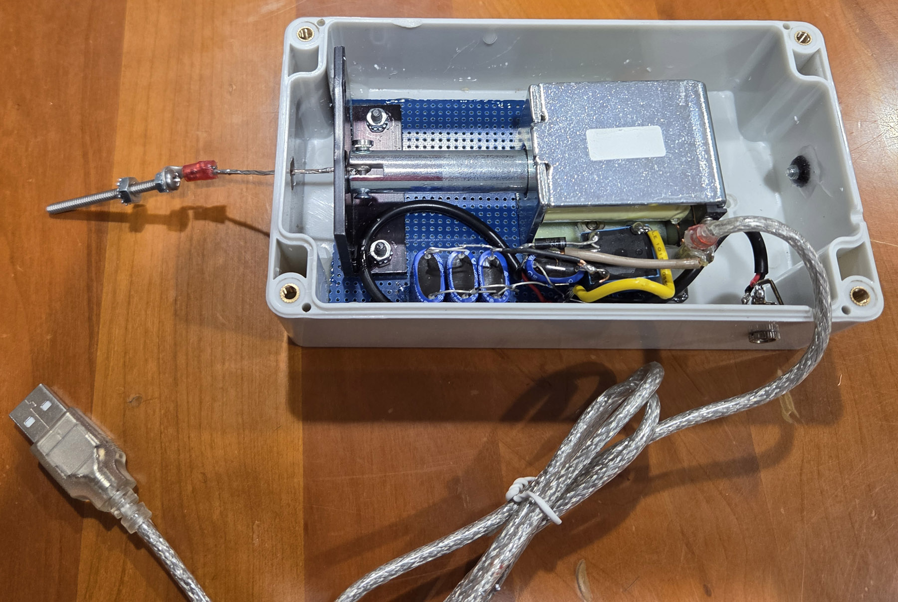
 I constructed the circuit on a small piece of vector board. This picture shows the solenoid in its fully
extended position (i.e. when there is no current in the solenoid coil). Then tension in the wire connected to
the flush lever keeps the plunger in this position (touching the plate) until the solenoid is engaged.
The black cable going to the right edge of the picture goes to a connector leading to the pushbutton and
the fat silver cable carries the 5VDC power from the power bank.
I constructed the circuit on a small piece of vector board. This picture shows the solenoid in its fully
extended position (i.e. when there is no current in the solenoid coil). Then tension in the wire connected to
the flush lever keeps the plunger in this position (touching the plate) until the solenoid is engaged.
The black cable going to the right edge of the picture goes to a connector leading to the pushbutton and
the fat silver cable carries the 5VDC power from the power bank.
 This picture shows the position of the solenoid when it is fully energized. The screw is now about 1 inch
closer to the circuit board which is enough to fully depress the flush lever. The metal plate is needed
to prevent the wire tension from pulling the plunger completely out of the solenoid. Conceivably you could
use the wall of the enclosure for this function but then you would need to be precise about where the circuit
board was mounted.
This picture shows the position of the solenoid when it is fully energized. The screw is now about 1 inch
closer to the circuit board which is enough to fully depress the flush lever. The metal plate is needed
to prevent the wire tension from pulling the plunger completely out of the solenoid. Conceivably you could
use the wall of the enclosure for this function but then you would need to be precise about where the circuit
board was mounted.
Click on any picture on this page to see a larger image.
(Then hit the back button to return to this page.)
 This shows the circuit board mounted inside the enclosure. (Actually I think I just epoxied it in.)
The connector on the side of the enclosure is for a cable going to the pushbutton. I originally put
that connector on the smaller side of the enclosure (near the right edge of this picture) but that
was when my plan was to glue the enclosure to the side of the toilet. But soon I realized that was
difficult and I decided to mount it on the floor next to the toilet. This meant I had to relocate
the connector. I plugged that hole and covered it with epoxy. I used a file to carve a small notch
in the enclosure so the silver power cable would have room to sneak thru.
This shows the circuit board mounted inside the enclosure. (Actually I think I just epoxied it in.)
The connector on the side of the enclosure is for a cable going to the pushbutton. I originally put
that connector on the smaller side of the enclosure (near the right edge of this picture) but that
was when my plan was to glue the enclosure to the side of the toilet. But soon I realized that was
difficult and I decided to mount it on the floor next to the toilet. This meant I had to relocate
the connector. I plugged that hole and covered it with epoxy. I used a file to carve a small notch
in the enclosure so the silver power cable would have room to sneak thru.
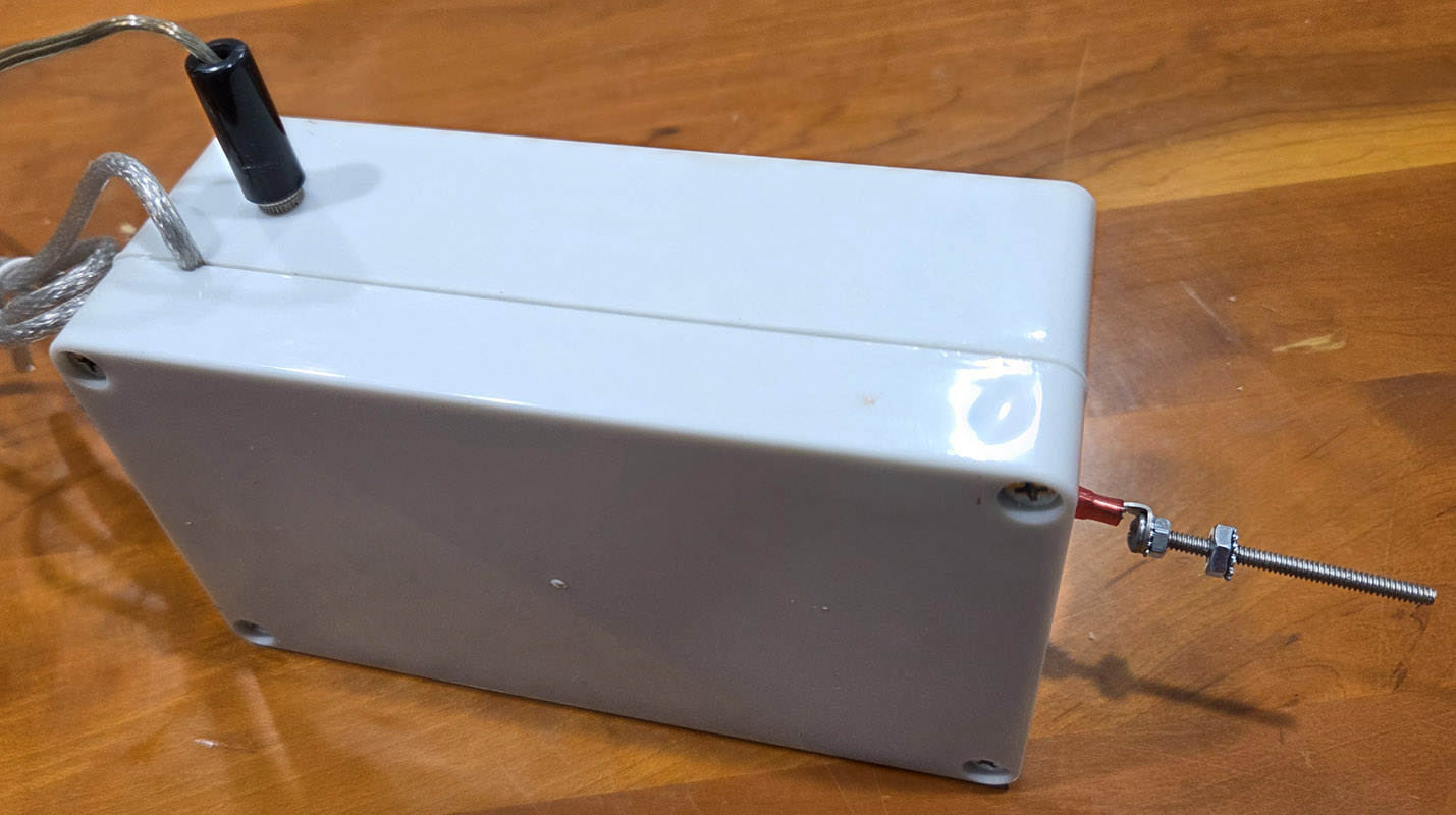 After screwing the cover on, the enclosure is ready to be mounted to the floor.
(This picture shows the enclosure with the solenoid in it's fully engaged position.)
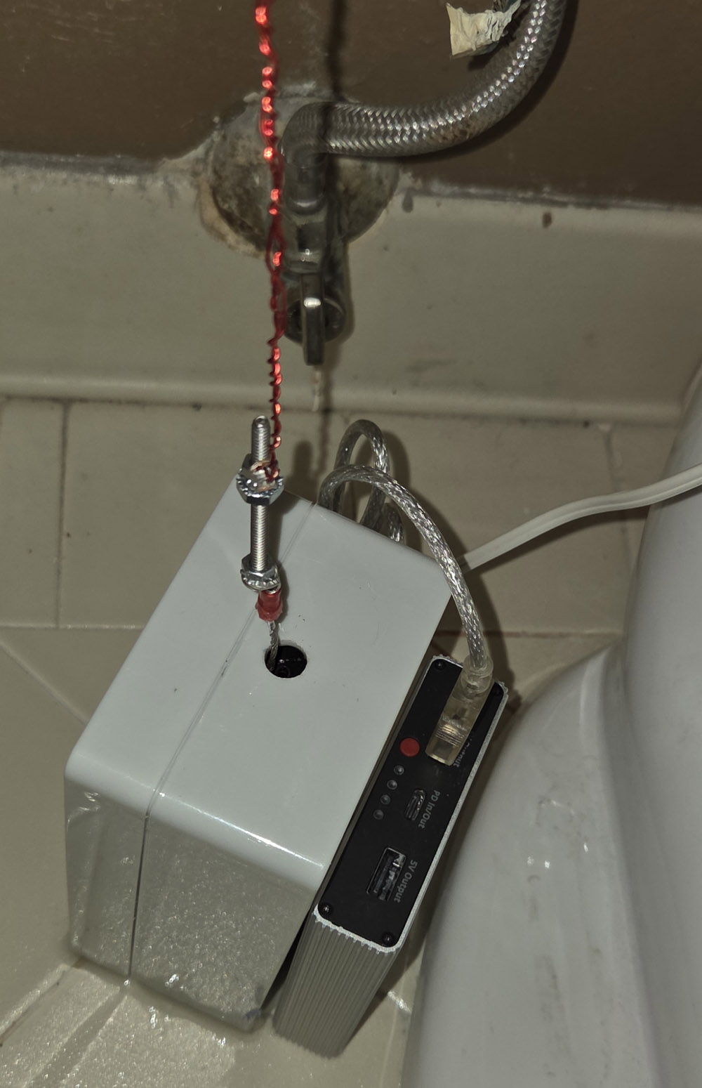 For simplicity I epoxied the enclosure directly onto the floor so that the solenoid was aligned
directly under the tip of the flush lever. I may regret this in 10 or 20 years when I have to remove
the enclosure to open it and change out the worn out super capacitors. It's hard to see from this
picture, but upper wire and lower wire are both attached to the screw using a crimp terminal. The
upper wire is secured to the screw with one nut below the crimp terminal and another nut above.
The tension on the wire can be adjusted by screwing the nuts towards or away from the screw head.
I found it worked best to increase the tension until there was little or no wiggle left in the
flush lever. (Normally the chain that lifts the flapper is loose enough that you can wiggle the
flush level somewhat without flushing the toilet.) The two conductor white cable is plugged into
the connector on the side of the enclosure and runs behind the toilet to the right side of the
toilet where the pushbutton is glued to the side. (See next picture). The power bank is not secured
to the floor or the enclosure. It just sits there on the floor, but it doesn't wander around because
of the stiffness of the silver cable. That allows the power bank to be easily removed when it needs
to be recharged.
For simplicity I epoxied the enclosure directly onto the floor so that the solenoid was aligned
directly under the tip of the flush lever. I may regret this in 10 or 20 years when I have to remove
the enclosure to open it and change out the worn out super capacitors. It's hard to see from this
picture, but upper wire and lower wire are both attached to the screw using a crimp terminal. The
upper wire is secured to the screw with one nut below the crimp terminal and another nut above.
The tension on the wire can be adjusted by screwing the nuts towards or away from the screw head.
I found it worked best to increase the tension until there was little or no wiggle left in the
flush lever. (Normally the chain that lifts the flapper is loose enough that you can wiggle the
flush level somewhat without flushing the toilet.) The two conductor white cable is plugged into
the connector on the side of the enclosure and runs behind the toilet to the right side of the
toilet where the pushbutton is glued to the side. (See next picture). The power bank is not secured
to the floor or the enclosure. It just sits there on the floor, but it doesn't wander around because
of the stiffness of the silver cable. That allows the power bank to be easily removed when it needs
to be recharged.
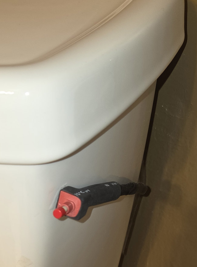 The button can be attached to the toilet in the most convenient spot for your preference. I liked
this spot on the right side just below the tank lid. I attached the button to the toilet with a
small dab of epoxy.
The button can be attached to the toilet in the most convenient spot for your preference. I liked
this spot on the right side just below the tank lid. I attached the button to the toilet with a
small dab of epoxy.
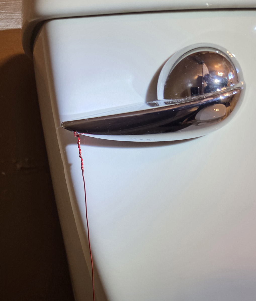 I drilled a small hole on the underside of the flush lever and threaded the bare copper wire thru
that hole and twisted the wire to securely attach it to the lever.
I drilled a small hole on the underside of the flush lever and threaded the bare copper wire thru
that hole and twisted the wire to securely attach it to the lever.
Success:
Click on the picture to see the video showing
what happens when the pushbutton is pressed.
Now that I have completed this design, I do like this toilet. It is satisfying that a feather
light touch on the pushbutton completes the perfect flush every time. And unlike most toilets,
I never have to worry about how much toilet paper I'm putting into the toilet. I haven't seen
a clog yet.
At some point (perhaps in 6 months) nothing will happen when I push the button
because the power bank has run out of charge. But while I'm recharging the power bank I
can still use the toilet by pushing the flush lever as the toilet manufacturer had intended.
That said, unless you like to tinker (like me), you should probably choose some other model the
next time you are in the market for a new toilet.