Fan Controller
I recently (2011) purchased a new desktop computer based on the Asus P8Z68-Vpro motherboard
with an Intel quad core I7-2600K CPU running at 4.6GHz.
Although the CPU draws only about 7 watts at idle, with all 8 threads running full out the
CPU draws about a 100 watts. So I knew my computer would need a good cooling system,
especially since my computer is located in the living room of my un-air-conditioned house.
So my computer included 4 low noise case fans as well as a large dual fan Noctua CPU cooler.
I also wanted my computer to be quiet, but because of the sophisticated temperature
sensing and fan control circuitry on this motherboard, I assumed the fans would be
turning slowly except perhaps when doing video processing or other compute intensive
tasks during a summer heat wave.
I was disappointed to find that this was not true. The first and most significant problem
is that the ASUS fan control software enforced a lower limit of 60% power for the case fans.
While the fans were certainly quieter at 60% than 100%, with four of them running is still
made a significant amount of noise. It seemed almost too incredible that with all this
seemingly well designed hardware and software, they would make it essentially useless to
me because of this one unmodifiable parameter. Yet indeed this was true. I considered
waiting for ASUS to fix this problem with a bios update, but there didn't seem to be a
way of finding out if this was even on their agenda or not.
The second problem was more my fault. The fans on the Noctua CPU are normal voltage controlled
fans. Some motherboards can control the rpm of these fans, but this particular motherboard
can only control the rpm of a CPU fan that uses the alternate PWM control. I could have, and
should have purchased a different CPU cooler that used PWM control. The system configurator/builder
should have flagged this incompatibility, but in their defense ASUS has very poor documentation
on this aspect of their design. The CPU fans must be PWM controlled and the case fans must be
voltage controlled, although this fact is nowhere documented.
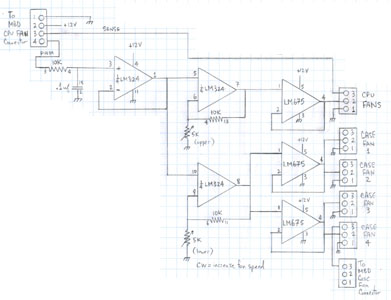 Eventually I decided to solve both problems by building my own fan controller. Here is a thumbnail
of the schematic of my fan controller. As with all the other pictures on this page, click on
the thumbnail to view the full size image. (Use the back button to return to the main page.)
Eventually I decided to solve both problems by building my own fan controller. Here is a thumbnail
of the schematic of my fan controller. As with all the other pictures on this page, click on
the thumbnail to view the full size image. (Use the back button to return to the main page.)
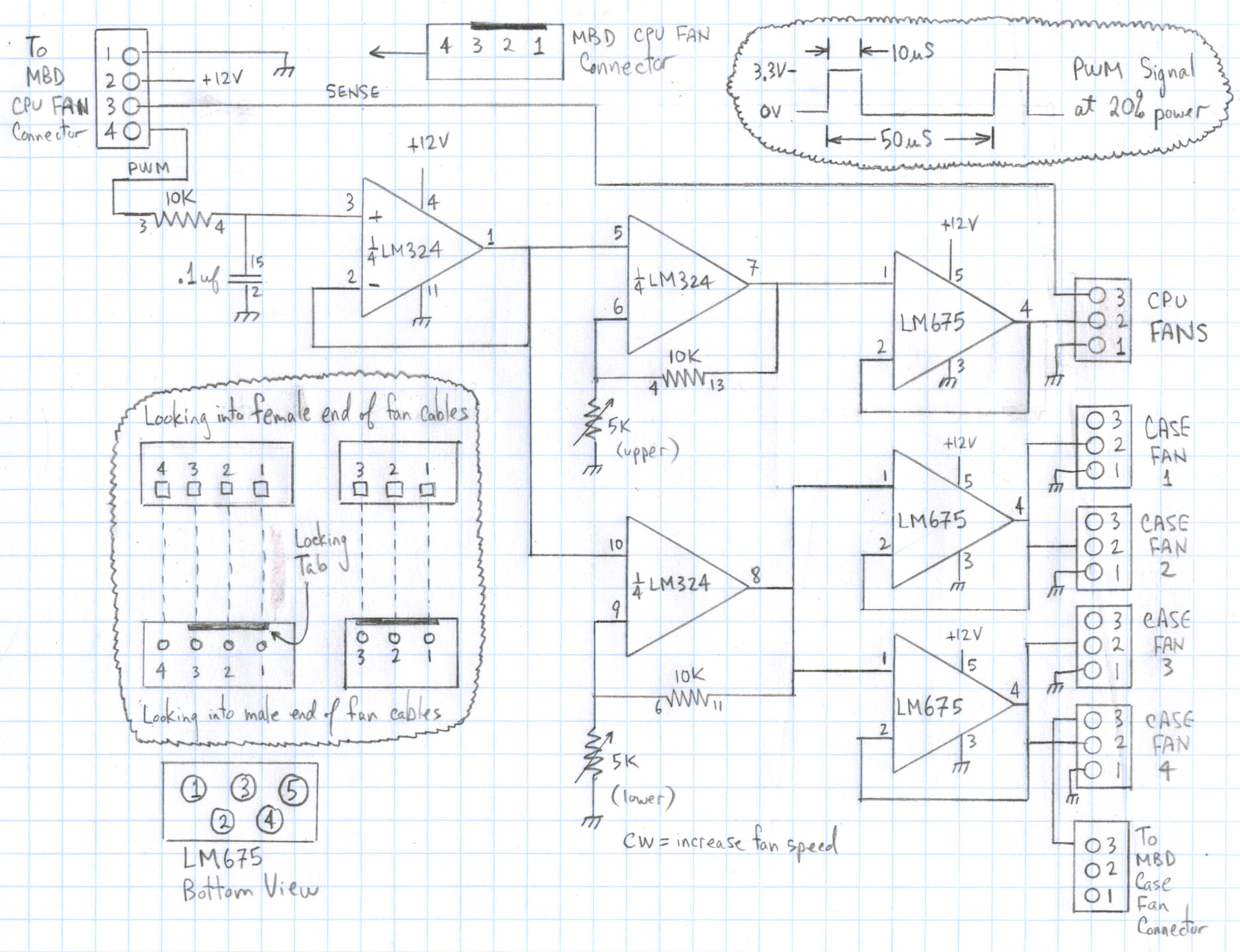
For simplicity, the CPU fan PWM signal from the motherboard is used to control
all the fans in the system. This means that the case fans will start spinning up
sooner after a compute intensive task begins, but I considered this an advantage.
The PWM signal is averaged by the RC circuit, then buffered by the first op-amp.
This is followed by two gain stages, one for the CPU fan and the other for the case
fans. Each gain of these gain stages is adjusted by a trimmer pot so that the fans
are spinning as slowly as possible when the system is cool. The amplified averaged
PCM signal is then used to drive the fans thru three high current op-amps (LM675)
each of which drives two fans. The sense signal from one of the case fans is fed
back to the motherboard (connecter near the bottom of the schematic)
so that the various fan monitoring programs can display the speed of the case fans.
(Note that the CPU fan sense signal is similarly passed to the motherboard.)
Fan speed test results:
Conveniently, the ASUS AI Suite has a CPU fan test button that slowly
cycles the fan power from 20% up to 80%, giving me an easy way to test
my circuit, and to record the results which are as follows:
| Pwr |
CPU rpm |
Case rpm |
| 20% | 450 | 320 |
| 30% | 690 | 450 |
| 40% | 860 | 600 |
| 50% | 1000 | 750 |
| 60% | 1030 | 830 |
| 70% | 1050 | 1000 |
| 100% | 1050 | 1000 |
The fan speeds at the 20% power level are slow enough that my computer is virtually silent
unless a very intensive compute task is in progress.
The ASUS AI Suite also allows one to choose from several fan profiles,
including a user programmable profile. I chose the user programmable
profile with the following breakpoints:
- 30 degrees, 21%
- 50 degrees, 100%
- 75 degrees, 100%
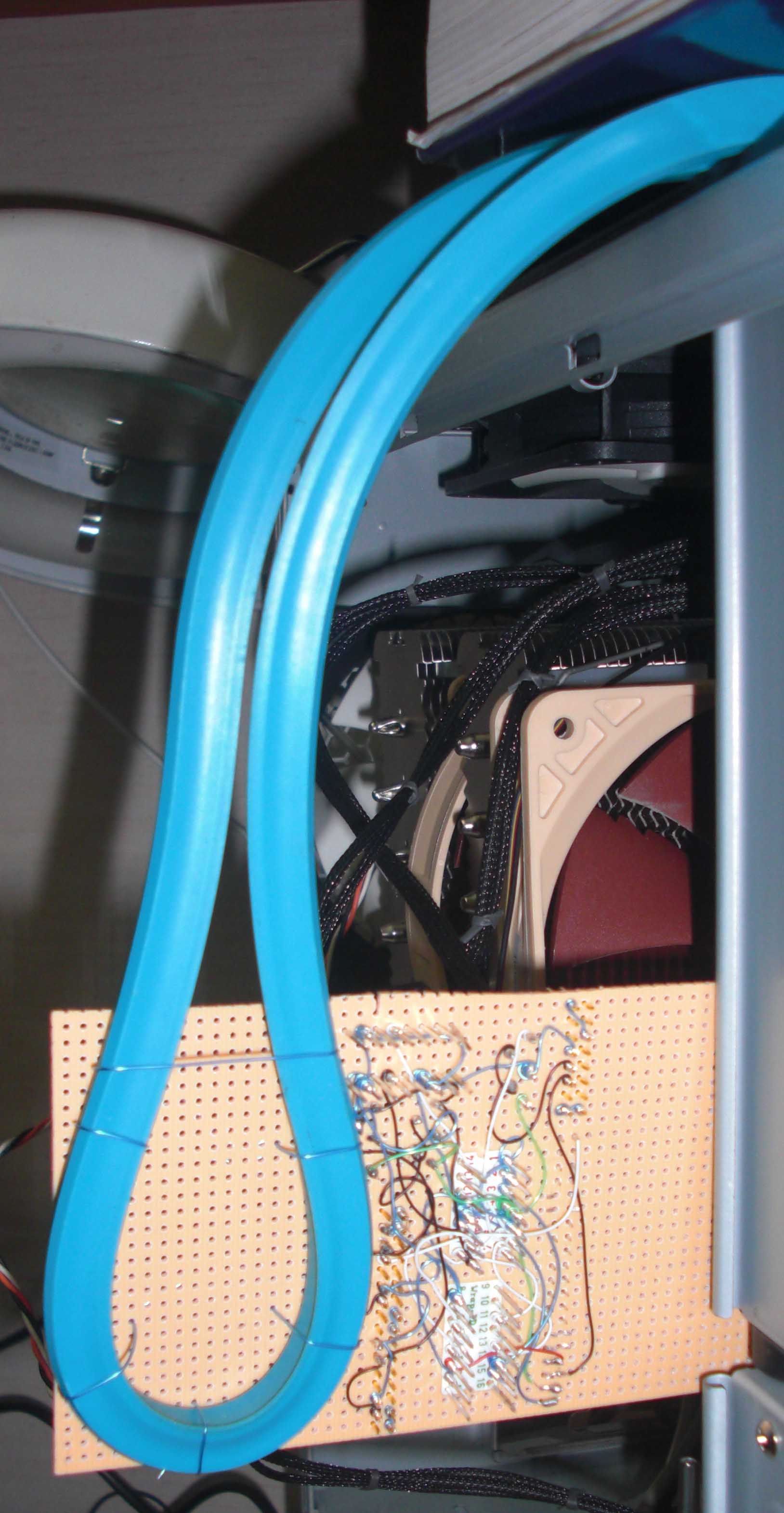
 Perhaps the only clever part of the effort was my method of temporarily mounting
the circuit board close enough that all the fan connections could be made yet
in a position that enabled access to the components for debugging purposes.
I wire-wrapped a stiff piece of rubber (a french curve actually) to the board and
then clamped the french curve to the top of the computer using a suitably heavy
text book. Of course I removed the french curve from the circuit board once the
correct operation of the circuit was verified.
Perhaps the only clever part of the effort was my method of temporarily mounting
the circuit board close enough that all the fan connections could be made yet
in a position that enabled access to the components for debugging purposes.
I wire-wrapped a stiff piece of rubber (a french curve actually) to the board and
then clamped the french curve to the top of the computer using a suitably heavy
text book. Of course I removed the french curve from the circuit board once the
correct operation of the circuit was verified.

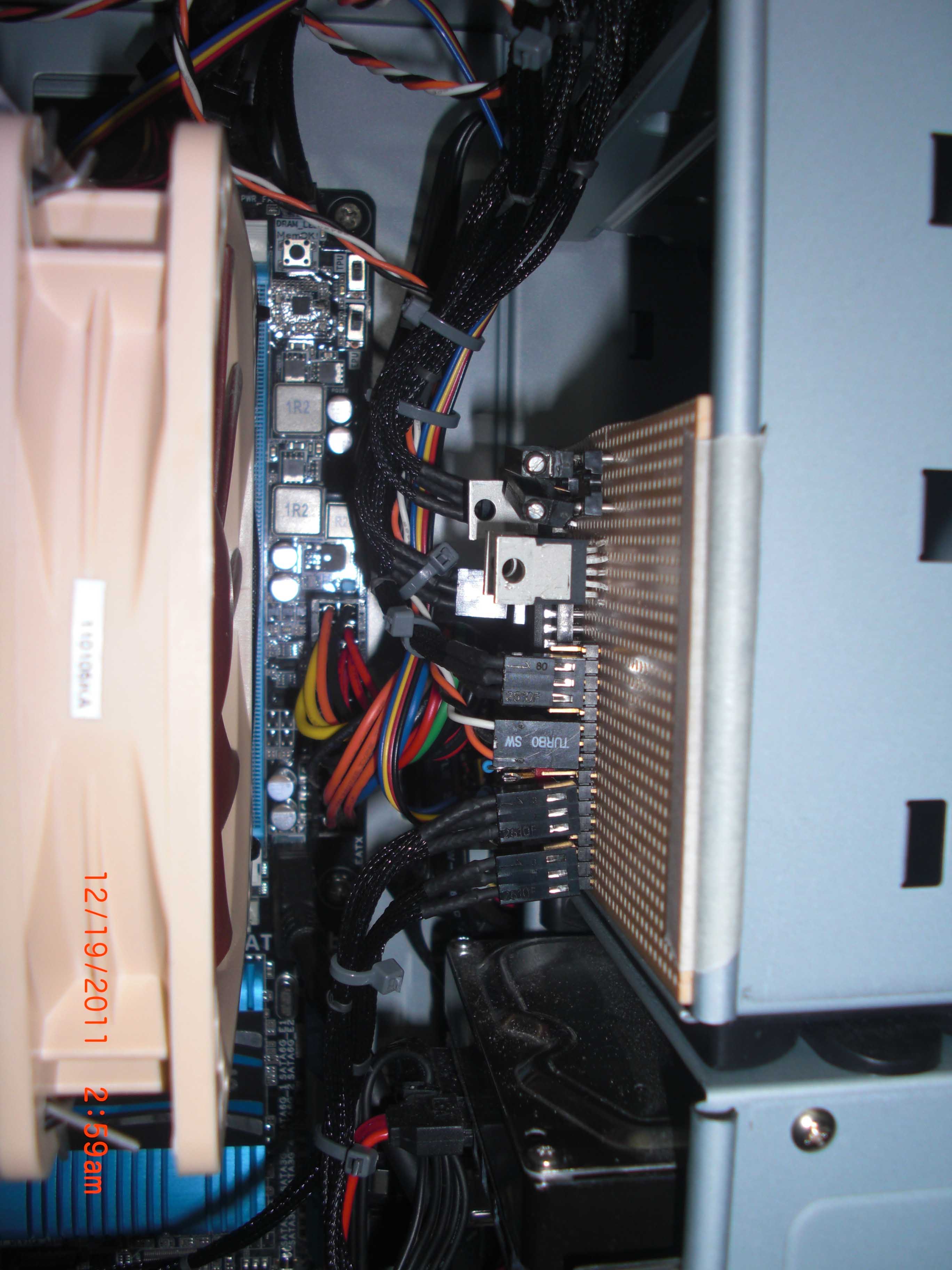
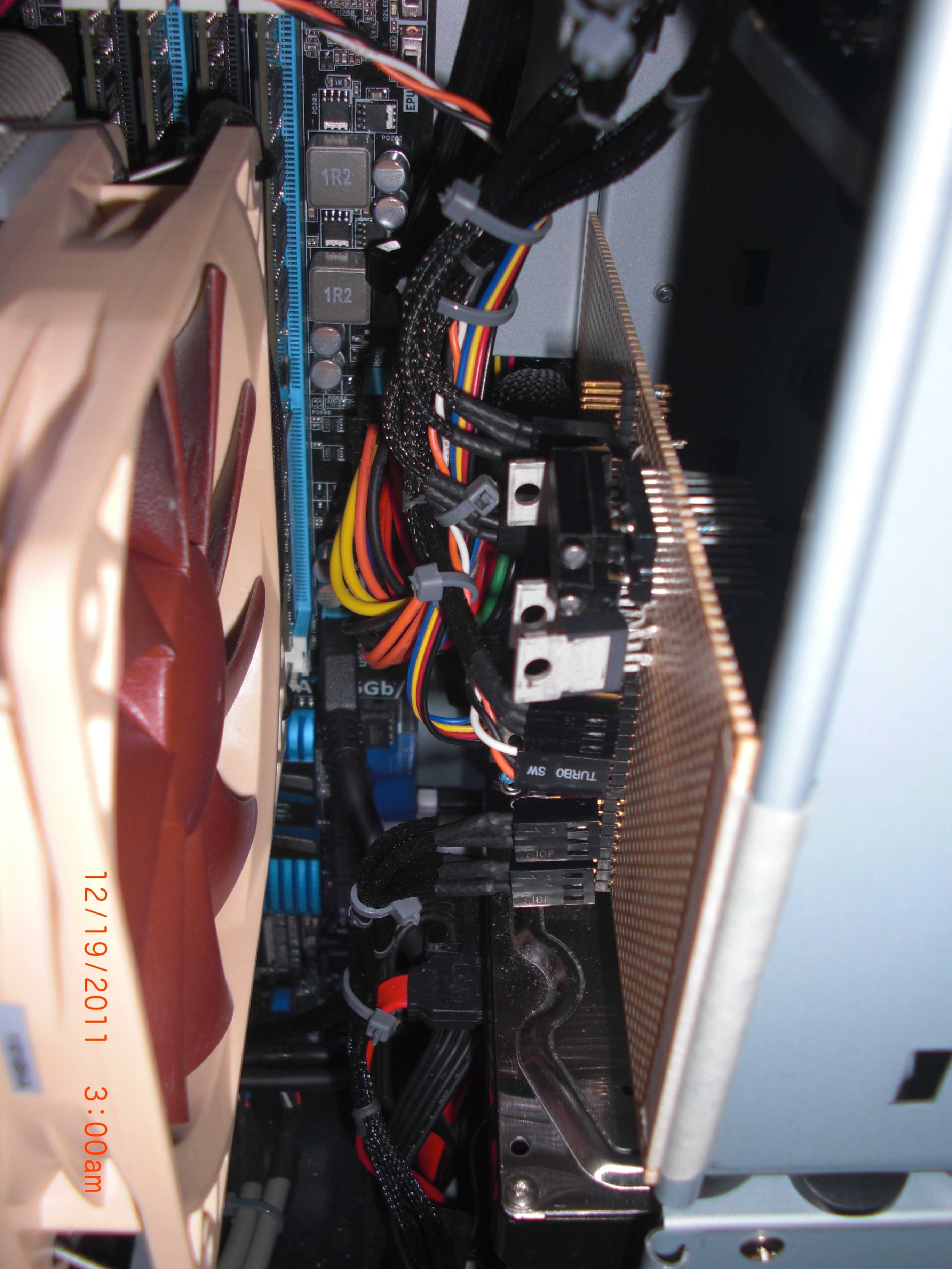
 Here are two pictures showing the board installed inside the computer. The
board is mounted on the back side of one of the unused drive bays. The fan
cables are tie wrapped in place so as not to impede air flow.
Here are two pictures showing the board installed inside the computer. The
board is mounted on the back side of one of the unused drive bays. The fan
cables are tie wrapped in place so as not to impede air flow.
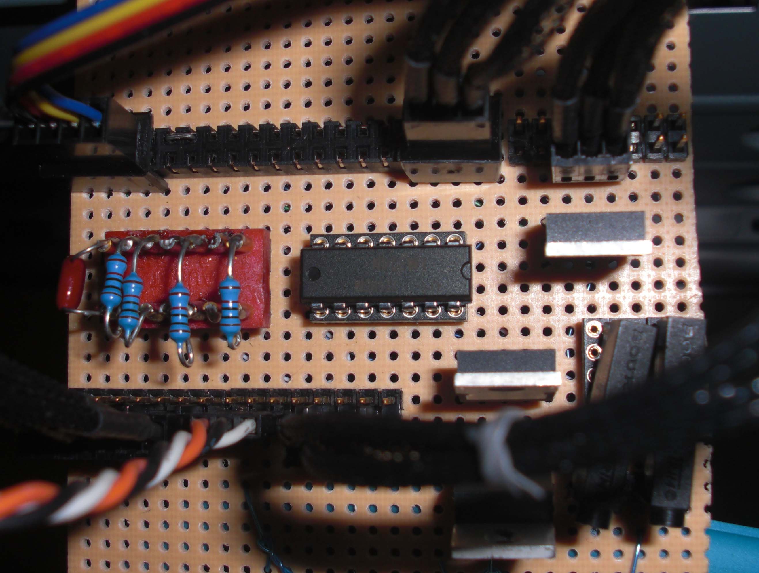
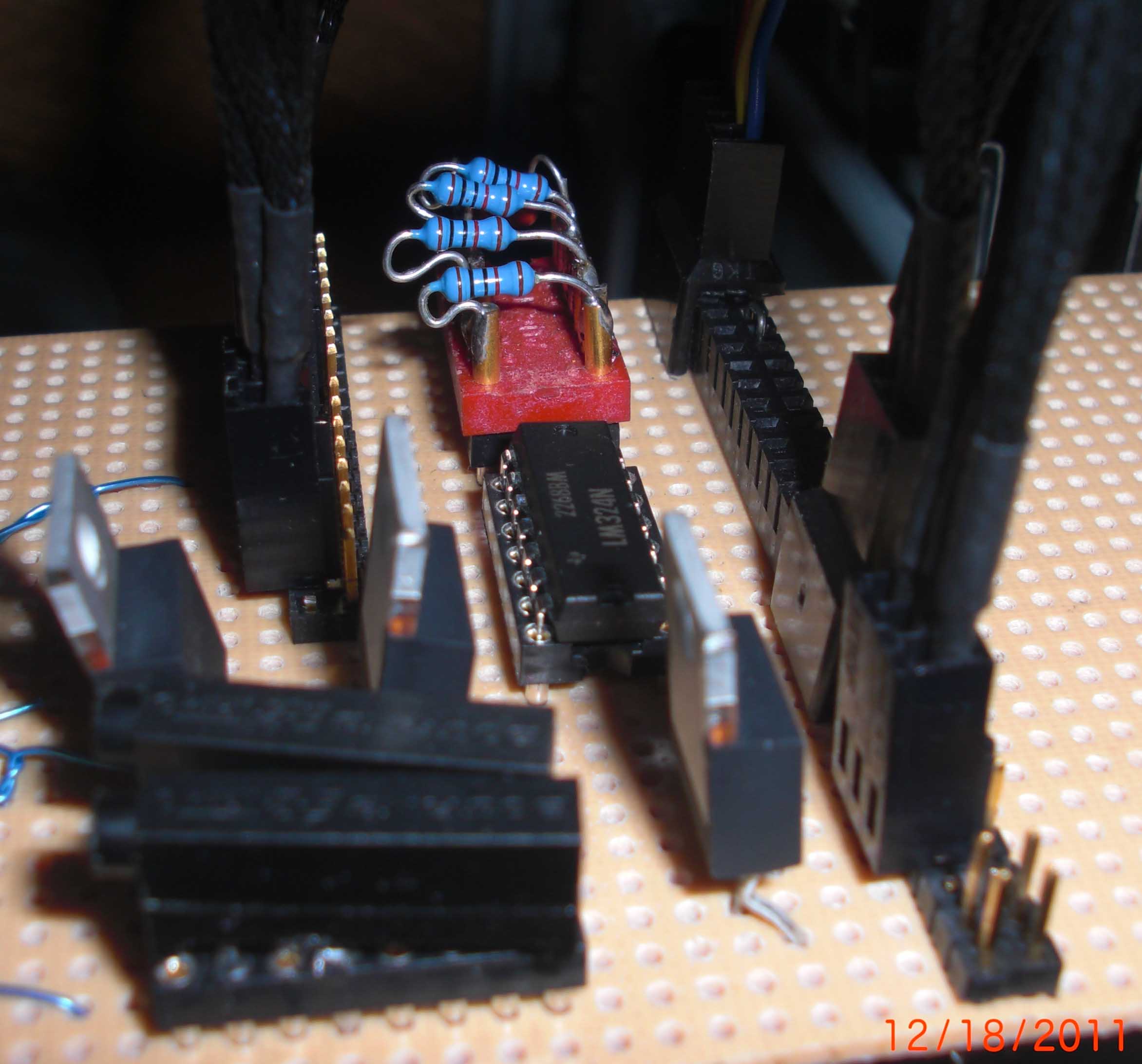
 Here are a few close-up views of the circuit board. Although the header
includes four 10k resistors, only three of them are actually used. Remember that
you can click on any of these pictures to view a higher resolution version.
Here are a few close-up views of the circuit board. Although the header
includes four 10k resistors, only three of them are actually used. Remember that
you can click on any of these pictures to view a higher resolution version.


 Perhaps the only clever part of the effort was my method of temporarily mounting
the circuit board close enough that all the fan connections could be made yet
in a position that enabled access to the components for debugging purposes.
I wire-wrapped a stiff piece of rubber (a french curve actually) to the board and
then clamped the french curve to the top of the computer using a suitably heavy
text book. Of course I removed the french curve from the circuit board once the
correct operation of the circuit was verified.
Perhaps the only clever part of the effort was my method of temporarily mounting
the circuit board close enough that all the fan connections could be made yet
in a position that enabled access to the components for debugging purposes.
I wire-wrapped a stiff piece of rubber (a french curve actually) to the board and
then clamped the french curve to the top of the computer using a suitably heavy
text book. Of course I removed the french curve from the circuit board once the
correct operation of the circuit was verified.
 Here are two pictures showing the board installed inside the computer. The
board is mounted on the back side of one of the unused drive bays. The fan
cables are tie wrapped in place so as not to impede air flow.
Here are two pictures showing the board installed inside the computer. The
board is mounted on the back side of one of the unused drive bays. The fan
cables are tie wrapped in place so as not to impede air flow.
 Here are a few close-up views of the circuit board. Although the header
includes four 10k resistors, only three of them are actually used. Remember that
you can click on any of these pictures to view a higher resolution version.
Here are a few close-up views of the circuit board. Although the header
includes four 10k resistors, only three of them are actually used. Remember that
you can click on any of these pictures to view a higher resolution version.